 |
RBE2 vs RBE3
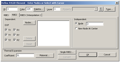
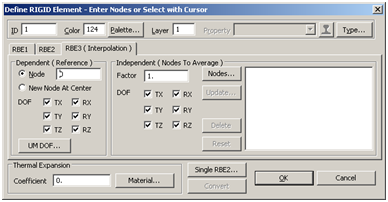
The RBE3 is similar in that it connects one node to one or more node(s) however it allows one dependent and one or more independent node(s). The DOFs are selectable on both the dependent and independent node sides. Independent nodes can have separate DOFs selected; this is different than the RBE2 Element formulation where only one set of DOFs is applied to all dependent nodes. In addition the node by node DOF selection, it is also possible to weight nodes effectivity which can be useful if a more specific node based distribution (rather than geometric) is required.
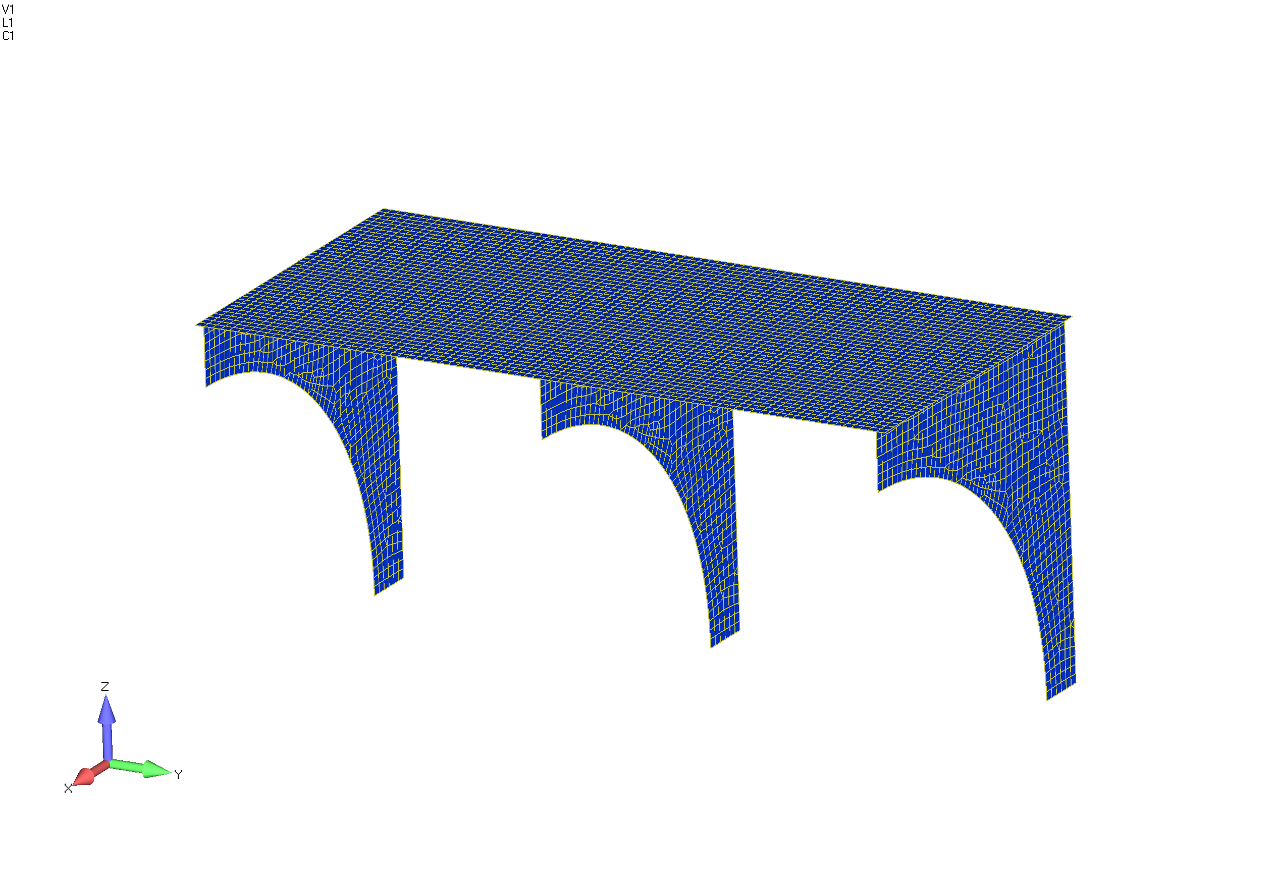
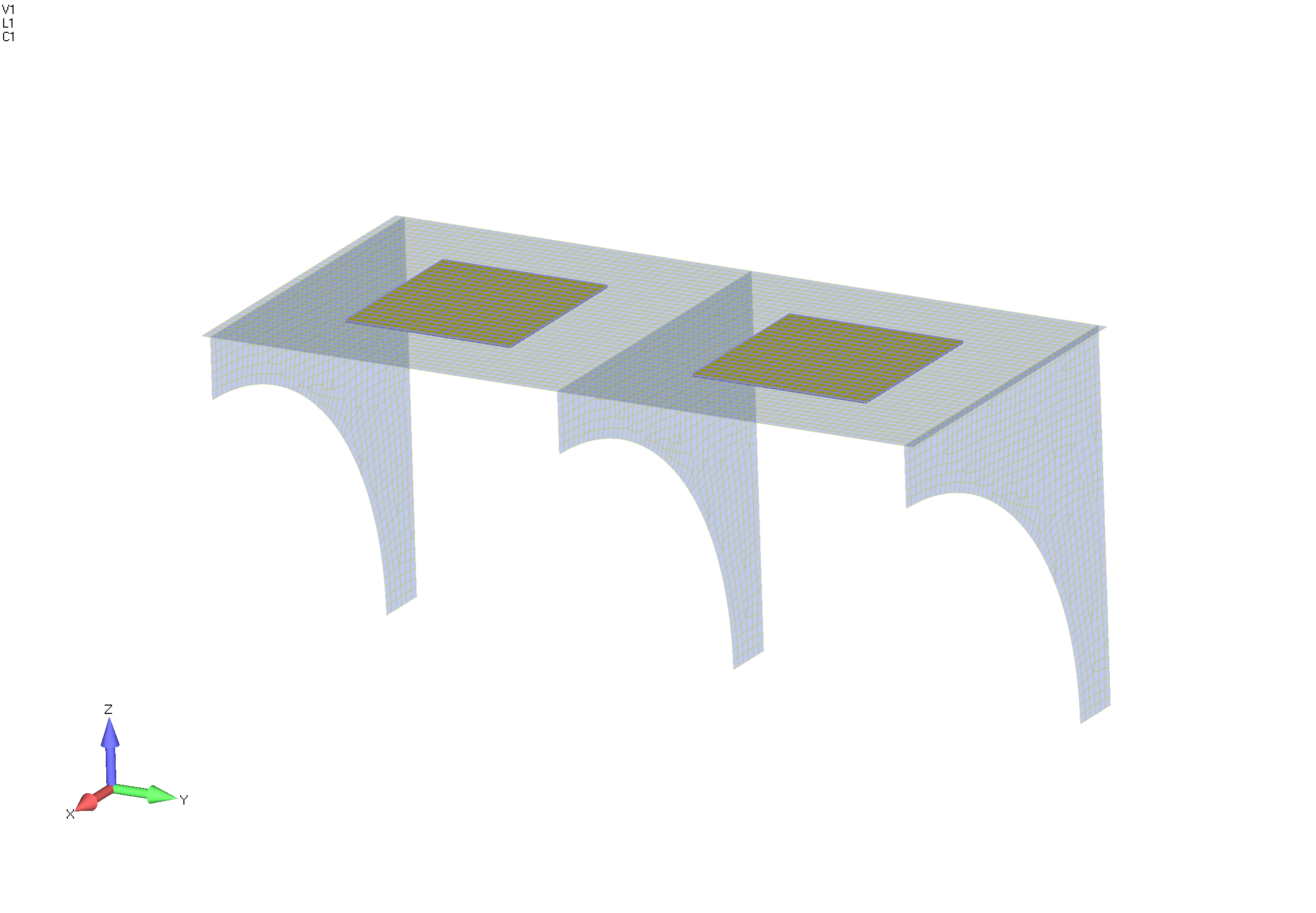
One of the most common uses for the RBE3 is to "smear" a load into a structure. The RBE2 impose stiffness and are often called "infinitely stiff", while the RBE3 is an interpolation element and does not impart additional stiffness to the model. To help illustrate this difference between the RBE2 and the RBE3 consider the following simple shelf model. The model is a two bay shelf and a vertical load is to be imparted in the center area of each bay.
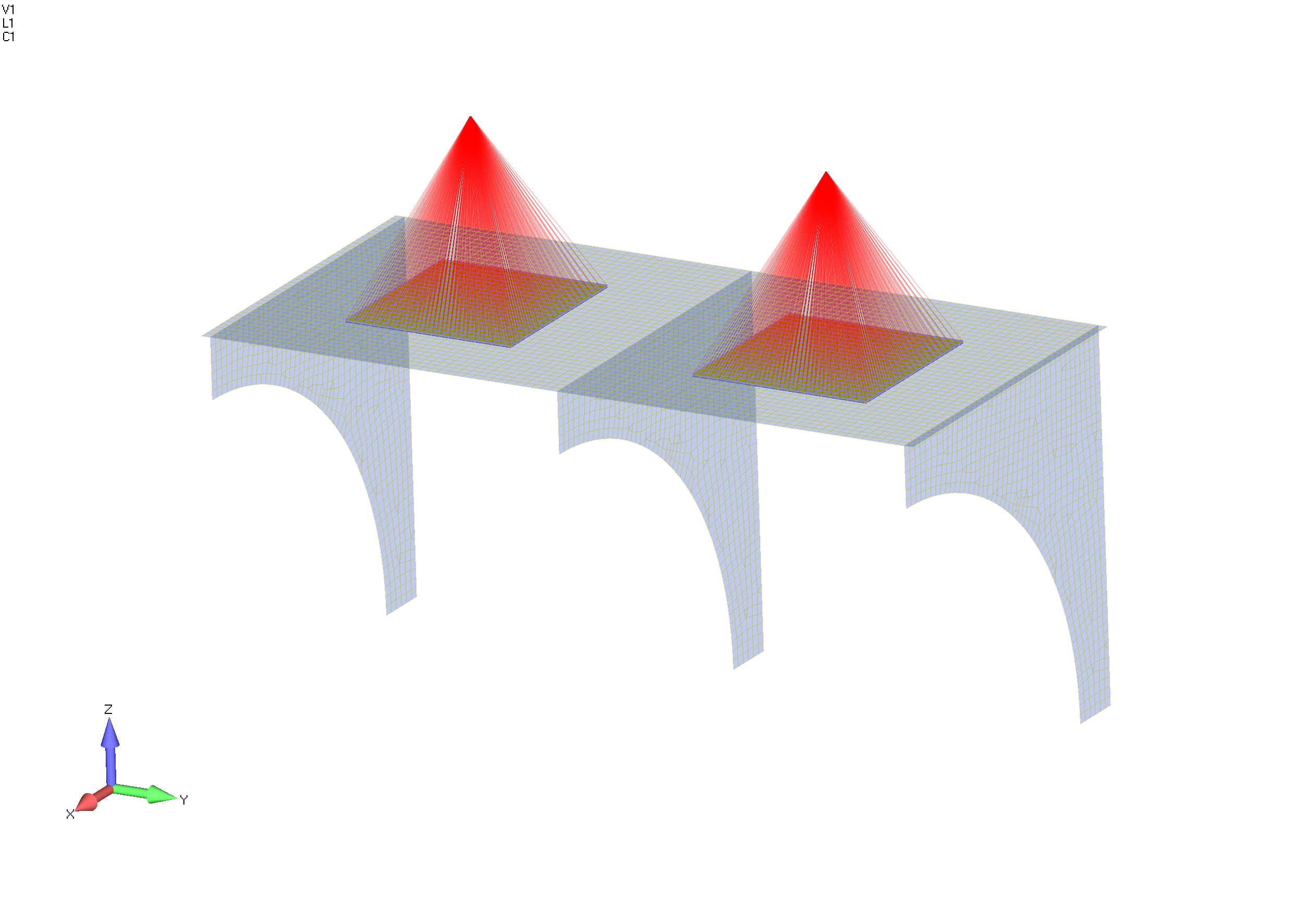
The left side bay of the shelf is modeled and loads are imparted with an RBE2 while the right side uses an RBE3. The "footprint" of each multi point constraint is identically shaped and positioned in its bay.
The back edge of the shelf and the back vertical leg of the supports are fixed while at the single node in each RBE a vertical force is applied.
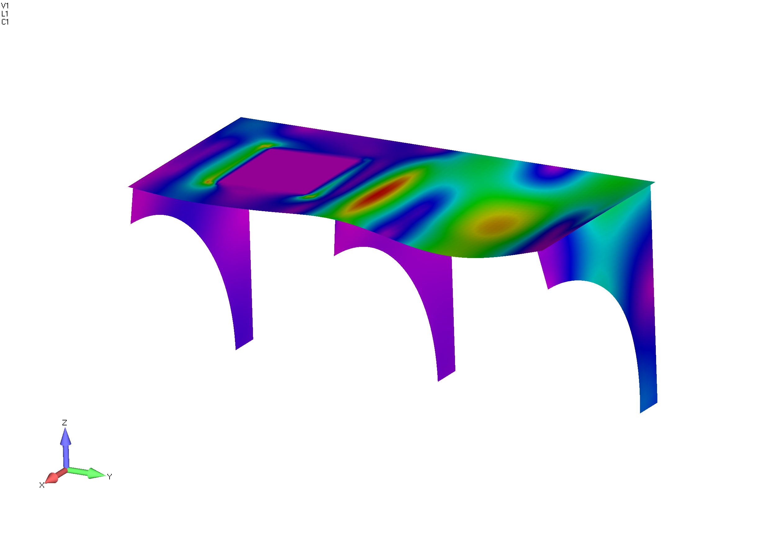
This effect is also apparent by investigating the stresses in the elements, as shown below:
It can be clearly seen the footprint under the RBE2 is stiffened by the formulation of the RBE2. Neither application, RBE2 or RBE3, is right or wrong; it simply depends on what the intent of the analysis is. Take for example the RBE2, on the left, if the down force is due to an inertial load of a box on the shelf an RBE2 is appropriate assuming the box is stiff relative to the shelf. The RBE3 however is more like a deformable body loading the shelf bay. |
.png)