 |
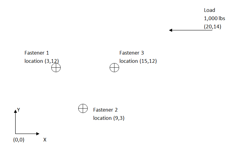
Simple Bolt Pattern When a load is reacted by a pattern of fasteners in shear, one method of determining the shear load in each fastener (or perhaps of more interest the maximum shear in the highest loaded fastener) is as follows. Consider the following configuration (distance in inches):
This classical method assumes rigid path from the load to the fastener pattern. Additionally, it assumes each fastener is able to react the load at the same time. This means that it assumes fabrication techniques that use hole filling or close tolerance holes so that each fastener begins reacting the load immediately. This example presumes that each fastener is identical (and thus "shares" the load equally based on geometric distribution only), though more advanced methods can be used which take size or material (stiffness) into account. Step 1: Find the centroid of the pattern. Since, for this example, each fastener is considered equal (diameter and material, or size and stiffness) the centroid of this pattern is the simple average: the X coordinate is: \begin{align} X & = \frac{ X_{coordinate fastener 1}+ X_{coordinate fastener 2}+ X_{coordinate fastener 3} }{ 3 } \\ X & = \frac{ 3+9+15 }{ 3 } \\ X & = 9 \end{align} the Y coordinate is: \begin{align} X & = \frac{ Y_{coordinate fastener 1}+ Y_{coordinate fastener 2}+ Y_{coordinate fastener 3} }{ 3 } \\ Y & = \frac{ 12+3+12 }{ 3 }\\ Y & = 9\\ \end{align} The centroid is therefore located at (9,9) as shown below.
Next, the applied load (1,000 lbs) is replaced by a statically equivalent load at the centroid just calculated: This results in a shear and moment when the load is "moved". The moment is calculated as follows: \begin{align} M_{@Centroid} & = (F_y*dx)-(F_x * dy)+ \\ M_{@Centroid} & = {(0*(20-10))}-{(-1,000 * (14-9))}+\\ M_{@Centroid} & = 5000\\ \end{align} This simplifies the schema to:
The reaction at each fastener can now be determined as a function of its distance from the centroid (this is because each fastener is the same size and material, or stiffness in this example) of the pattern and the load at the centroid. The reaction at each fastener has two components, the first is perpendicular (normal) to the vector from the fastener to the centroid, and second the portion reacting the fastener's portion of the shear load. This first portion will have components in the X and Y directions, therefore it is more useful to determine the component directions since they will be combined with the second part of the loading. For the first part of the load (the part that reacts the moment) the following is completed. Determining the X direction of this part of the load: \begin{align} p_{X direction from moment} & = \frac{Moment_{Applied at Centroid}*dist_{in Y fastener to centroid}}{number of fasteners * \sum{dist_{all fasteners}^2}}\\\ \\\end{align} Determining the Y direction of this part of the load: \begin{align} p_{Y direction from moment} & = \frac{Moment_{Applied at Centroid}*dist_{in X fastener to centroid}}{number of fasteners * \sum{dist_{all fasteners}^2}}\\\ \\\end{align} The second part is as follows: \begin{align} p_{from shear} & = \frac{applied shear}{number of fasteners}\\ p_{from shear} & = \frac{-1000}{3}\\ p_{from shear} & = -333.33\\\ \\\end{align} This second part of the load is the same for all fasteners, calculating the first part for each fastener the distance to centroid is required, as well as the square of their sum: Fastener 1: \begin{align} dist_1 & = \sqrt{(X_{fast} - X_{centroid})^2(Y_{fast} - Y_{centroid})^2} \\ dist_1 & = \sqrt{(3- 9)^2+(12 - 9)^2} \\ dist_1 & = \sqrt{(-6)^2+(3)^2} \\ dist_1 & = 6.71 \\\end{align} Fastener 2: \begin{align} dist_2 & = \sqrt{(X_{fast} - X_{centroid})^2(Y_{fast} - Y_{centroid})^2} \\ dist_2 & = \sqrt{(9- 9)^2+(3 - 9)^2} \\ dist_1 & = \sqrt{(0)^2+(-6)^2} \\ dist_2 & = 6.00 \\\end{align} Fastener 3: \begin{align} dist_3 & = \sqrt{(X_{fast} - X_{centroid})^2(Y_{fast} - Y_{centroid})^2} \\ dist_3 & = \sqrt{(15- 9)^2+(12 - 9)^2} \\ dist_1 & = \sqrt{(6)^2+(3)^2} \\ dist_3 & = 6.71 \\\end{align} Summing each of these: \begin{align} \sum{dist_{all fasteners}^2} & = dist_1^2+dist_2^2+dist_3^2 \\ \sum{dist_{all fasteners}^2} & = 6.71^2+6.00^2+6.71^2 \\ \sum{dist_{all fasteners}^2} & = 126 \\\end{align} The, first part of the load, resultant load in each fastener can now be determined as: Fastener 1
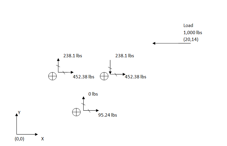
In the X direction: \begin{align} p_{X direction from moment} & = \frac{Moment_{Applied at Centroid}*dist_{in Y fastener to centroid}}{\sum{dist_{all fasteners}^2}}\\ p_{X direction from moment} & = \frac{5000*(12-9)}{126}\\ p_{X direction from moment} & = 119.04 \\\end{align} In the Y direction: \begin{align} p_{Y direction from moment} & = \frac{-Moment_{Applied at Centroid}*dist_{in X fastener to centroid}}{\sum{dist_{all fasteners}^2}}\\p_{Y direction from moment} & = \frac{-5000*(3-9)}{126}\\ p_{Y direction from moment} & = 238.1 \\\end{align} These can now be combined with the shear load (part two of the load) as follows: \begin{align} p_{X} & = 119.04 -(-333.33)\\ p_{X} & = 452.38\\ \\\end{align} The resultant of the in plane loads is the shear the fastener experiences and is calculated: \begin{align} p_{shearfastener} & = \sqrt{p_x^2 +p_y ^2}\\ p_{shearfastener} & = \sqrt{452.38^2 + 238.1 ^2}\\ p_{shearfastener} & =511.21\\ \\\end{align} Fastener 2: In the X direction: \begin{align} p_{X direction from moment} & = \frac{Moment_{Applied at Centroid}*dist_{in Y fastener to centroid}}{ \sum{dist_{all fasteners}^2}}\\ p_{X direction from moment} & = \frac{5000*(3-9)}{126}\\ p_{X direction from moment} & = -238.01\\\ \\\end{align} In the Y direction: \begin{align} p_{Y direction from moment} & = \frac{Moment_{Applied at Centroid}*dist_{in X fastener to centroid}}{ \sum{dist_{all fasteners}^2}}\\ p_{Y direction from moment} & = \frac{5000*(9-9)}{126}\\ p_{Y direction from moment} & = 0\\\ \\\end{align} These can now be combined with the shear load (part two of the load) as follows: \begin{align} p_{X} & = -238.1-(-333.33)\\ p_{X} & = 95.23\\ \\\end{align} The resultant of the in plane loads is the shear the fastener experiences and is calculated: \begin{align} p_{shearfastener} & = \sqrt{p_x^2 +p_y ^2}\\ p_{shearfastener} & = \sqrt{95.23^2 + 0 ^2}\\ p_{shearfastener} & =95.23\\ \\\end{align} Fastener 3 In the X direction: \begin{align} p_{X direction from moment} & = \frac{Moment_{Applied at Centroid}*dist_{in Y fastener to centroid}}{\sum{dist_{all fasteners}^2}}\\ p_{X direction from moment} & = \frac{5000*(12-9)}{126}\\ p_{X direction from moment} & = 119.04 \\\ \\\end{align} In the Y direction: \begin{align} p_{Y direction from moment} & = \frac{-Moment_{Applied at Centroid}*dist_{in X fastener to centroid}}{\sum{dist_{all fasteners}^2}}\\ p_{Y direction from moment} & = \frac{-5000*(15-9)}{126}\\ p_{Y direction from moment} & = -238.09 \\\ \\\end{align} These can now be combined with the shear load (part two of the load) as follows: \begin{align} p_{X} & = 119.04 -(-333.33)\\ p_{X} & = -452.38\\ \\\end{align} The resultant of the in plane loads is the shear the fastener experiences and is calculated: \begin{align} p_{shearfastener} & = \sqrt{p_x^2 +p_y ^2}\\ p_{shearfastener} & = \sqrt{452.38^2 + -238.09 ^2}\\ p_{shearfastener} & =511.21\\ \\\end{align} Summarizing and checking the results:
The maximum fastener shear is a tie in fastener 1 and 3 at 512 lbs.
As always with calculation they should be checked. The sum of the fastener forces should be equal and opposite to the applied load.
OK, now that we have the basics, go ahead and give it a try. You can use this handy bolt pattern load calculator to check your work.
As discussed in the Simple Bolt Pattern (classical method) the sum of the fastener reactions should be equal and opposite to the applied load. This means static equilibrium is maintained. This article was inspired by: Young, Warren C., Richard G. Budynas, and Raymond Jefferson. Roark. Roark's Formulas for Stress and Strain. New York: McGraw-Hill, 2002.
Other great sources of reading material in the literature on this topic may find interesting include: Bruhm, Elmer F. Analysis and Design of Flight Vehicle Structures. [S.l.]: S.R. Jacobs, 1973. Chapter D.1 - Fittings and Connections. Bolted and Riveted As discussed in the Simple Bolt Pattern (classical method) the sum of the fastener reactions should be equal and opposite to the applied load. This means static equilibrium is maintained. This is also true with CAE and it is a good practice to do a "sanity check" and ask yourself do my FEA results make sense?
|